Week 02: Computer-aided Design
Introduction
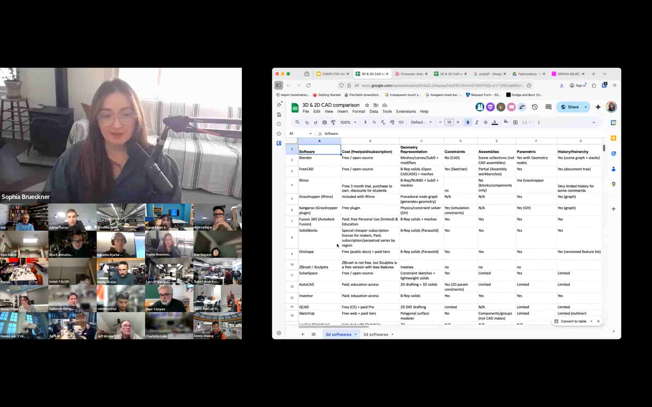
This week, Sophia and Kenny introduced us to the fundamentals of 2D and 3D design.
I have always enjoyed drawing by hand, and I often sketch ideas first on paper.
However, hand drawings can fade over time, get damaged, or be difficult to edit precisely. Thanks for the tech development, I found the tools like Canva and PowerPoint are great for starters like me to do visual work, even design some event posters are not diffcult for me.
Even so, I was mostly using them in a practical way, without really understanding how digital images and models are constructed.
This week helped me start building that foundation. I began to understand that in digital fabrication, design is not only about making something look nice. It is also about understanding file types, geometry, paths, and how machines read design data.
Understanding Bitmap and Vector Graphics
What is a Bitmap (Raster) Image?
A bitmap image is made of tiny squares called pixels. Each pixel stores a specific color value. For example, a 1200 × 800 image contains 960,000 pixels, and the computer stores the color information for every single one of them.
When we zoom in on a bitmap image, the pixels become larger, and the image starts to look blurry or jagged. This is because the number of pixels does not increase, they simply get stretched.
Common bitmap formats include: JPG / JPEG, PNG, GIF, BMP, TIFF. Normally, we used JPG and PNG, PNG is a lossless image format that keeps edges, text, and transparency crisp, so it is usually best for logos, icons, screenshots, and graphics with a transparent background. JPEG is a lossy format that produces much smaller files, so it is usually better for photos and other web images where file size matters more than perfect detail.
Bitmap images are ideal for Photographs, Scanned images, Complex color gradients, Textures, etc.
They are excellent for storing detailed color information but are not suitable for scaling up.
What is a Vector Image?
A vector image is completely different. Instead of storing pixels, it stores mathematical descriptions of shapes, such as: Points, Lines, Curves, Polygons.
For example, instead of storing thousands of pixels to describe a circle, a vector file simply stores the mathematical formula of a circle (center position and radius).
When we scale a vector image up or down, the computer recalculates the formula, so the image always remains sharp and clear.
Common vector formats include: SVG, EPS, PDF, AI
Vector graphics are ideal for: Logos, Icons, Posters, Technical drawings, Laser cutting files, CNC paths, PCB outlines.
For digital fabrication, vector files are essential because machines follow paths, not pixels.
Tools I Explored: GIMP and Inkscape
After understanding the theory, I explored two open-source tools: GIMP and Inkscape. All are free to use!
GIMP
GNU Image Manipulation Program is a raster image editor, similar to Photoshop. It works directly with pixels.
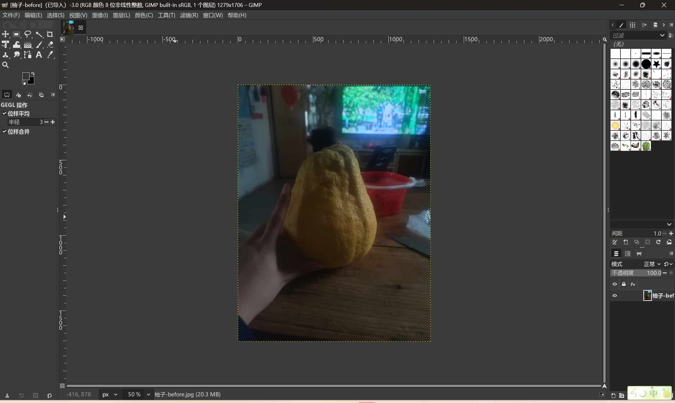
It is suitable for Photo editing, Cropping and resizing, Color correction, Removing backgrounds, Cleaning scanned images. Its native format is XCF, which preserves layers, but it can export to formats like PNG and JPG. GIMP is mainly used when working with photographs or pixel-based images.
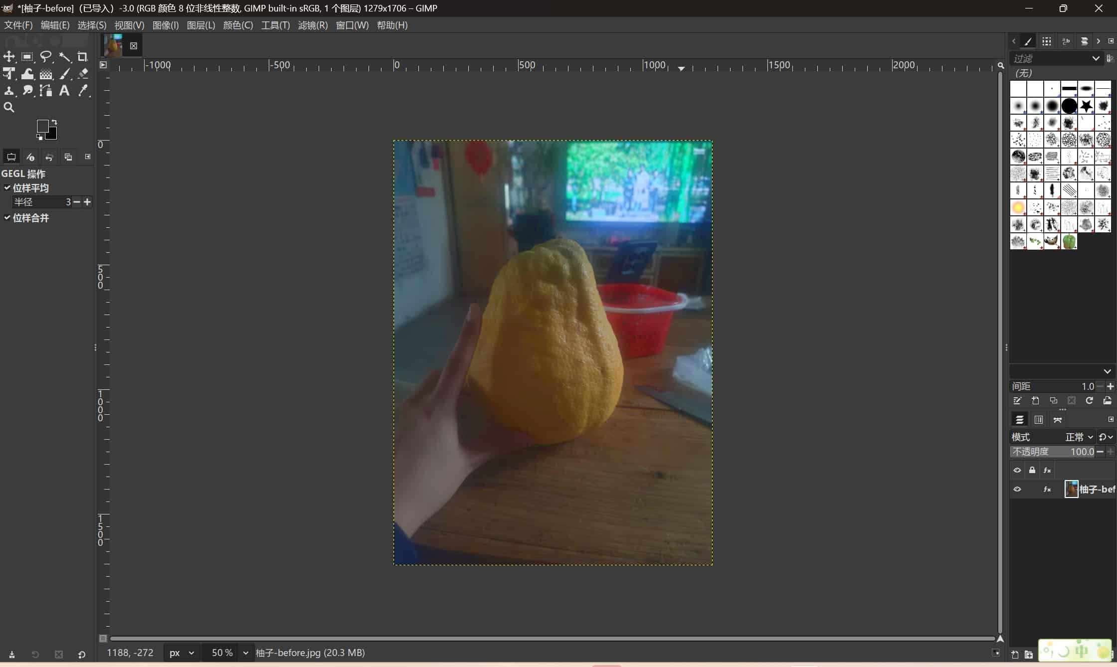
To practice, I edited a photo of a grapefruit. The original image looked a little dark, so I increased the color saturation by 10.
Inkscape
Inkscape is a vector graphics editor, similar to Adobe Illustrator. It works primarily with SVG files and allows editing of: Paths, Nodes, Strokes, Fills, Text.
Inkscape is commonly used to Create logos and icons, Design posters, Prepare files for laser cutting or vinyl cutting, Precisely control dimensions in millimeters. For fabrication workflows, Inkscape is very important because machines require clean vector paths.
Typical workflow: from bitmap to vector
A common workflow combining both tools could be:
- Clean or adjust a bitmap image in GIMP (e.g., remove background, improve contrast).
- Export it as PNG.
- Import the image into Inkscape.
- Use “Trace Bitmap” to convert it into vector paths.
- Adjust nodes and paths.
- Export as SVG or DXF for fabrication.
This helped me understand how both tools support different stages of design preparation.
My 2D Practice This Week
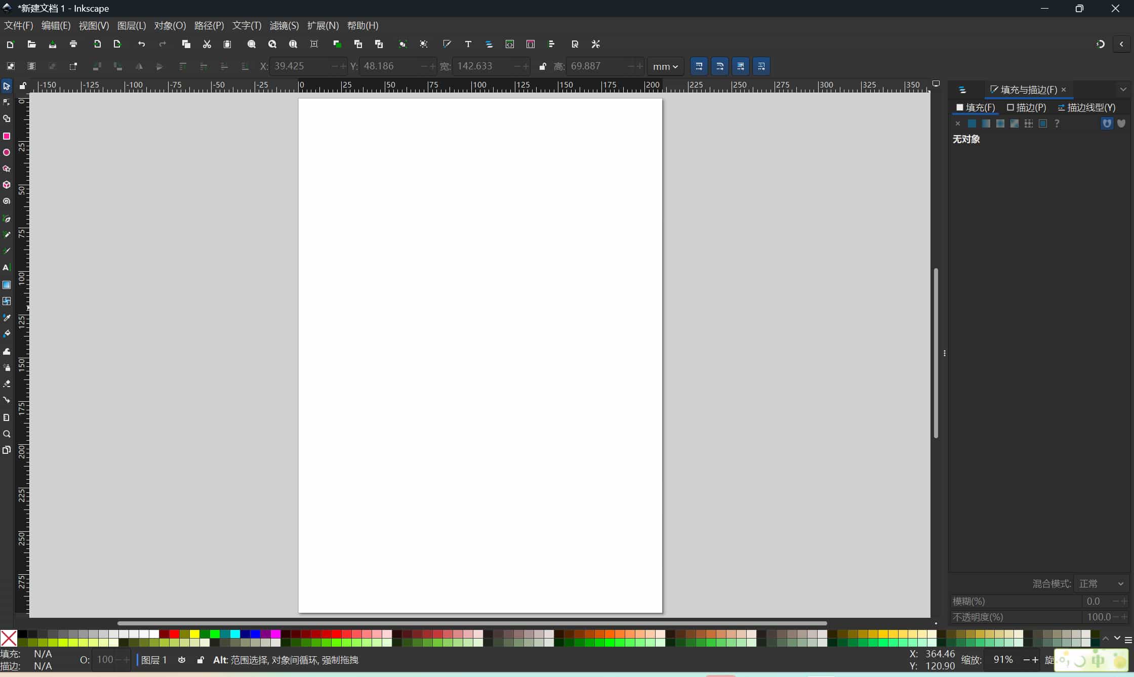
This week, I downloaded Inkscape on Windows and started practicing basic operations.
I learned how to:
Adjust the page size (Ctrl + Shift + D), set the document size to 30 cm × 30 cm, and draw basic shapes like circles.
Use path tools, experiment with curve drawing.
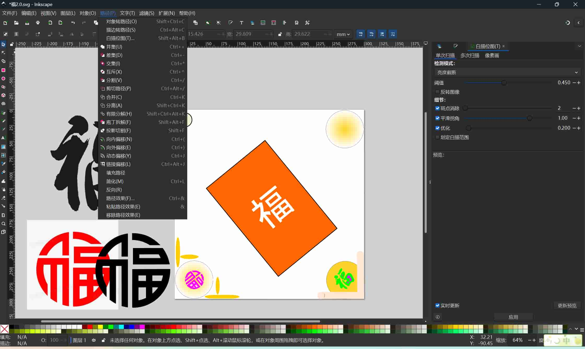
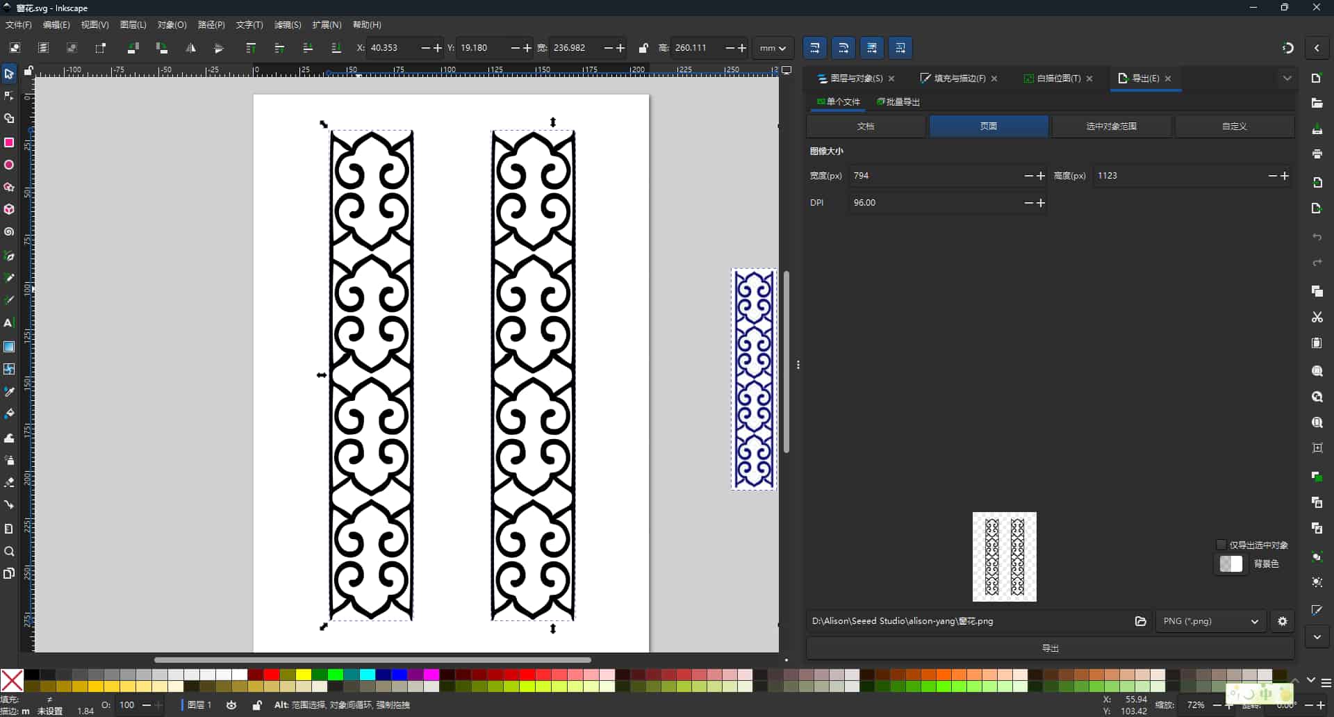
I wanted to decorate a Chinese character “Fu” (福) with some ornamental curves. I found that Inkscape is much more precise than PowerPoint for this kind of design because I can directly control paths and nodes.
What is a Bézier Curve?
While learning Inkscape, I encountered the concept of Bézier curves.
A Bézier curve is a mathematically defined curve controlled by points and handles. When using the curve tool in Inkscape, each segment is created using: A start point, An end point, Control handles, By moving the control handles, the shape of the curve changes smoothly.
Almost all vector graphics, fonts, and SVG shapes are built using Bézier curves. Understanding this concept helped me realize that vector graphics are based on mathematical logic rather than pixels.
Introduction to 3D Design Concepts
In addition to 2D design, we were also introduced to basic 3D modeling concepts.
CSG (Constructive Solid Geometry) is a way of building complex 3D forms by combining simple shapes such as:Cubes, Cylinders, Spheres.
Using Boolean operations: Union (add), Difference (subtract), Intersection
For example, subtracting a cylinder from a cube creates a cube with a hole.
This idea is especially useful for designing mechanical parts, boxes, enclosures, and 3D printed components.
Trying Onshape
I also started learning Onshape, which is a cloud-based 3D CAD platform. One thing I liked is that I do not need to install heavy software locally, because it runs in a browser. It also includes version control and collaboration features, which makes it feel modern and convenient.
At the same time, I also noticed a difficulty: if the internet connection is unstable, the workflow becomes less smooth. Sometimes reconnection interrupts the design process. Even so, Onshape gave me my first clearer experience of how structured 3D design works.
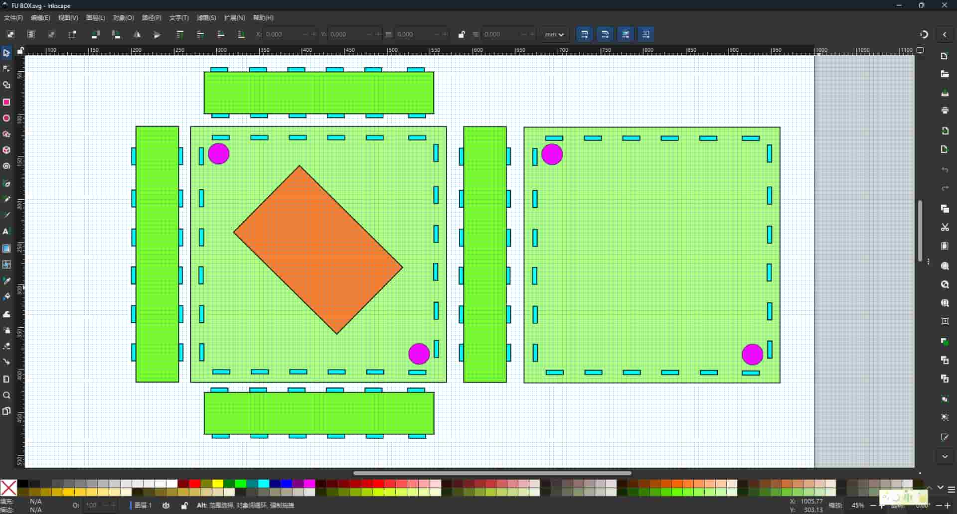
Updated Design Practice
After becoming a little more familiar with Inkscape and Onshape, I tried to apply them to my own final project ideas. I began designing a frame structure like a box, with a screen opening and two additional holes for a switch and decoration. I set the size to 300 x 300 mm and tried to leave extra space for decorative elements.
For the decoration, I explored different directions. I thought about using window-style patterns, sticker-like motifs, or laser-cut decorative elements.
This part of the week felt especially meaningful, because I was no longer only learning software functions. I was starting to connect design tools with my own project ideas.
This week helped me understand:
- the difference between bitmap and vector graphics
- why vector files are important for digital fabrication
- how GIMP and Inkscape serve different purposes
- how Bezier curves define vector shapes
- the basic logic of CSG in 3D modeling
- how design tools can support my final project ideas
This week helped me move from casual visual editing toward a more fabrication-oriented way of thinking. For me, that was the most important progress.